The air compressor cooling water pump is an important part of the whole air compressor system. It is an important cooling device to ensure the safe and stable operation of the air compressor. The cooling water circulation reduces the exhaust temperature and cools the lubricating oil to achieve the cooling air compressor. purpose. The air cooling system of the air compressor includes a water tank, a water tank, an electric water pump, a pipe, a water filter, and a valve. The cooling water circulation system must be started before starting the air compressor, and the air pressure protection function of the air compressor itself cannot be started. Therefore, realizing the remote control and automatic control of the air compressor cooling water pump is an important guarantee for the long-term and stable operation of the entire air compressor system. Each 2 air compressors are supplied with cooling water from a water tank. The overall structure and circulation mode of the pump cooling system are as shown. Each water tank outlet is connected to two cooling water pumps. Under normal circumstances, one of the two water pumps is in working condition. One is used as a backup. When the running water pump fails, it switches to the standby water pump to ensure the supply of cooling water from the air compressor.
1 control system overall structure air compressor cooling water pump control system with the field control cabinet as the control core, through the sensor to achieve the collection of monitoring parameters of the cooling water pump, and through the PLC programming procedures for data centralized processing, the host computer using configuration software to cool The control and data display screen of the water pump are developed and designed. The upper computer and the field control cabinet communicate and data exchange through the Ethernet ring network, and the video surveillance camera is used to realize real-time video monitoring of the cooling water pump unit.
The overall structure and circulation mode of the pump cooling system 2 Data acquisition and control system The data acquisition and processing system of the air compressor cooling water pump unit is composed of the sensor parts and the field control cabinet that collect the various operating parameters of the cooling water pump. The structure is as shown in the figure. As the core of data acquisition and processing, Siemens programmable controller 224XP model PLC installs pressure sensor, temperature sensor, vibration sensor and electric parameter acquisition module on the control cabinet, motor unit and its output pipeline of the cooling water pump. The temperature and vibration signals are collected by the EM231 analog quantity acquisition module. The collection of various electric parameters of the cooling water pump is realized by the EDA9033A electric parameter acquisition module and the transformer. Each electric parameter acquisition module and the corresponding external transformer are installed separately. In the explosion-proof power distribution cabinet of the cooling water pump, a plurality of electrical parameter acquisition modules are connected to the communication port of the CPU through the RS485 bus. The CPU of the 224 XP model PLC has two data communication ports, and the other data communication port realizes remote communication and data interaction with the host computer.
Data acquisition and processing system The control of the air compressor cooling water pump is divided into two modes: manual control and automatic control. The configuration of the upper machine can realize the conversion of two modes. Under the manual control state, the operator can directly in the dispatching room. The start-stop operation is performed on the cooling water pump by configuring the control screen; when the system needs to be unattended, the system can be switched to the automatic control state, and the system determines the system fault according to the pressure of the pump pipeline.
The control flow chart of the air compressor cooling water pump is as shown in the figure. After the water tank is filled with water, the water inlet valve is opened and the water pump motor is started. After the delay time is reached, the water outlet valve is opened, and the water pump starts to inject water into the pipeline, and the water pressure in the pipeline begins. Ascending, the control system delays the determination of the water pressure of the pipeline. After the delay time is reached, the water pressure collected by the pressure sensor is compared with the set pressure value (0.2 MPa), if the pipeline water pressure is greater than the set pressure. Value, equipment is normal; if the water pressure of the pipeline is less than 0.2MPa, it indicates that there is a fault in the cooling water pump system, which may be caused by water shortage of the water tank or abnormal operation of the water pump. The system controls the motor and the water valve to close, and starts to fill the water tank after the water tank is filled with water. The system starts again in sequence. If the water pressure of the pipeline reaches the set value after the delay time expires, it indicates that the water tank is out of water and the pump motor is running normally. Otherwise, the system determines that the system is faulty and switches to the standby machine.
Cooling water pump control process PC remote monitoring system Air compressor cooling water pump remote monitoring system with Kingview software as the development platform, the cooling pump unit data monitoring, remote control, video monitoring integration, to achieve air compressor cooling water pump Remote control of operating status, real-time display of various operating parameters and equipment status of pump motor, real-time video monitoring of on-site of cooling water pump unit, over-limit alarm of various parameters, storage and recall.
The air compressor cooling water pump remote monitoring screen is as shown. The remote control of the cooling water pump, the inlet valve, the outlet valve, the water supply valve and the exhaust valve can be realized by the configuration screen of the upper water cooling water pump, and the equipment running state, water pump failure and water tank failure of each cooling water pump can also be realized. The remote control state and the pipeline water pressure are displayed in real time to ensure that the operator knows the working status of the cooling water pump at the first time. The monitoring of other data of the cooling water pump can be realized through the data query function.
In order to ensure the safety and long-term stable operation of the air compressor cooling water pump, the fault diagnosis expert system of the air compressor cooling water pump is constructed, and the expert knowledge and field experience are used effectively to accurately locate the system fault of the air compressor cooling water pump. Eliminate in time. The system uses the diagnostic method based on fault tree analysis to construct a fault diagnosis expert system for the air compressor cooling water pump, providing the field operators and maintenance personnel with accurate system failure reasons and maintenance plans.
Taking the vibration diagnosis of the air compressor cooling water pump motor as an example, after entering the cooling water pump fault diagnosis expert system, select the motor vibration over-diagnosis module to enter the motor vibration over-diagnosis screen.
First, add the symptom of the vibration that is too large. After the addition is completed, click the “Diagnostics†button, and the diagnosis result and reliability of the obtained cooling water pump failure are as shown. At the same time, the system's fault solution can be obtained as shown.
8, please choose the towel minus: credibility in the leveling" bad also æˆ a degree * A 帱 speed Ming X increase add 1 remove failure analysis 1 solution vibration too large fault diagnosis results vibration too large fault solution
6300 Series Deep Groove Ball Bearing
6300 Series Deep Groove Ball Bearing
Deep groove ball bearing are simple in design, non-separable, suitable for high and even very high speeds and are robust in operation, requiring little maintenance.
Deep-groove bearings have higher load ratings for their size than shallow-groove , but are also less tolerant of misalignment of the inner and outer races.
They are suitable for precision instrument, low noise electromotor, automobile and motorcycle, etc. It is the the most widely used bearing type.
6300 Series - Medium Series Ball Bearings – Ideal for heavier load capacity
Our Advantages:
1. More than ten years bearing products exporting experiences.
2. OEM order and Non-Standard Bearing order can be accepted.
3. Many sizes of bearing are available. Large quantity bearing can be provided.
4. To respect customers, you can choose the loading port.
5. A certain number of free sample can be provide to support our customer's after-sale services and warranty.
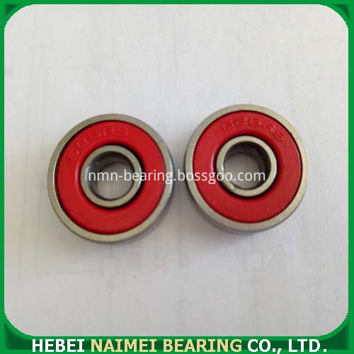
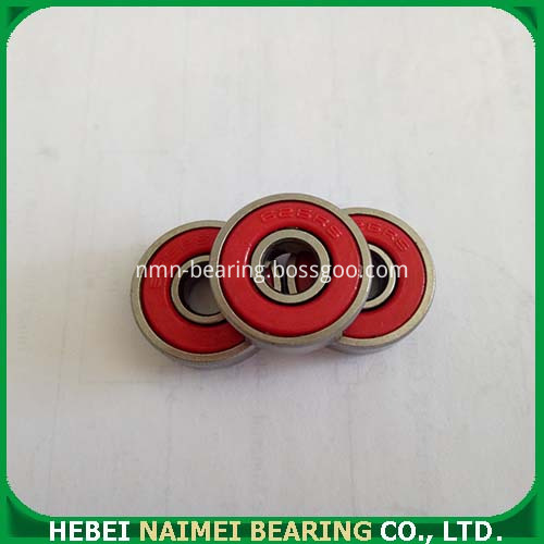
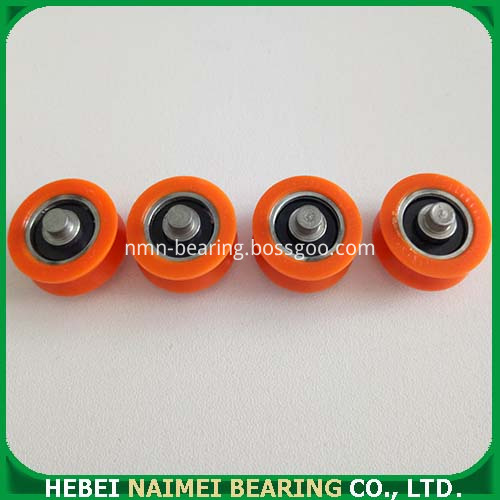
Product Photos:
Packing:
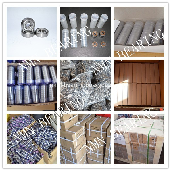
1 Industry package: 200pcs/plastic bag, 2000pcs /carbon , 50 cartons/pallet ,
2 Tube Package: 10PCS/tube,then put in Carton and Pallet
3 Single Package: 1PC/single box, then put in Carton and Pallet
And also we can pack according to your requirement.
Packing Photo:
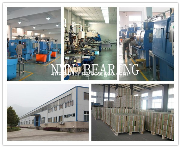
Workshop:
Shippment:

Exhibition:

6300 Series Deep Groove Ball Bearing,6300 Radial Ball Bearing,6300 Series Metric Ball Bearing
Hebei Naimei Bearing Co., Ltd. , https://www.nmn-bearing.com