China was the earliest country to build a ship lock. In the thirty-three years of Qinshihuang (formerly 214), the steep canal on the Lingqu was constructed by using the gate on the first gate to adjust the water level difference between the front and the back of the gate to achieve the goal of navigating the ship by overcoming the water level difference. In the Song Dynasty, the Xihe River (now the canal between Huai'an and Huaiyin, Jiangsu Province) built a steep gate with water transmission equipment. It is the prototype of modern ship locks. The Dutch built a single gate in the 12th century, and Italy began construction of a ship lock in the 14th century. In the 20th century, a large number of modern ship locks were built in the United States, Germany, the Soviet Union, and China. The scale of the inland navigation lock has reached a length of 360 meters in the lock chamber, a width of 34.5 meters in the lock chamber, and a water depth of 5 meters. The largest shiplock in China is the Gezhouba ship lock. The sluice gate is 280 meters long, 34 meters wide, and the threshold water depth is 5 meters.
The lock is composed of a gate with a gate and a valve, a lock chamber where the ship is placed, an upstream and downstream approach channel for guiding the ship into the lock chamber, a water delivery system for filling and discharging the lock chamber, and opening and closing of the gate and valve. Mechanical and control system components. The procedure for the vessel to cross the gate from the downstream approach channel upstream is to use the water delivery system to make the room water level flush with the water level in the downstream approach channel, open the first gate of the lower gate, the vessel enters the chamber, and closes the lower gate gate to the chamber. Irrigation to the water level is at the same level as the upstream approach channel, and the first gate of the upper gate is opened, and the vessel enters the upstream approach channel. When the ship sails from the upstream approach channel to the downstream approach channel, its procedure is reversed.

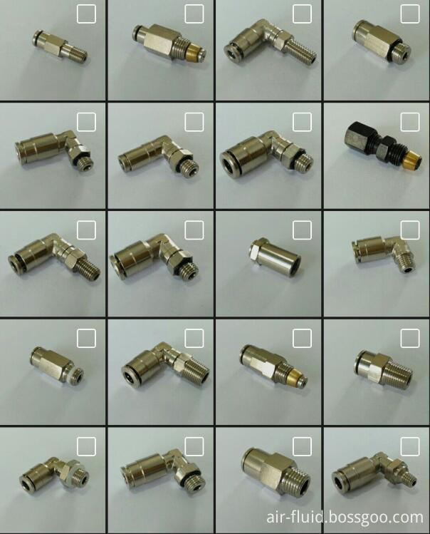
The Ningbo Air-Fluid BSPT Thread Brass Nickel-Plated Push in fittings with slot structure on Brass Collet is,which is milled by Auto-CNC Machines to assure the even distance between the tooth to tooth. This way can guarantee the precision & sharp claw to catch the tube hose firmly & steadily.
The Tee Connector ,Elbow ,Y Connector and Banjo Fittings are being forged with high compactness to avoid the space inside the solid fittings' body, The Polished Surface Treatment on the Forged fittings to wipe off the burr, spot and oil,the good character is the high adhesive power of nickel plating on its Surface.
BSPT Thread Brass Nickel-Plated Push in Fittings, the Max Woking Pressure 1000 PSI and Temp Range -20 To 120 Deg ,The forged body of Elbow , Y Connector , Run Tee and Branch Tee series fittings .
BSPT Brass Nickel-Plated Push in Fittings
Brass Nickel-Plated, Air-Fluid Brass Nickel-Plated, Bspt Brass Nickel-Plated Push In Fittings
Ningbo Air-Fluid Pneumatic Components Co., Ltd , http://www.air-fittings.com