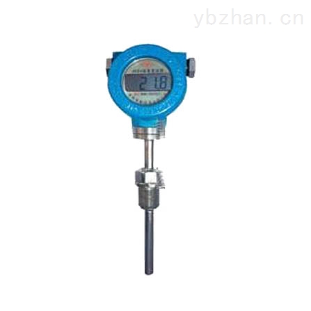
WZPB integrated temperature transmitter is a perfect combination of temperature sensor and transmitter. It converts the temperature signal in the range of -200~+1600°C to the electric signal of 2~4mA to 2mA DC to the display in a very simple way . , regulators, recorders, DCS, etc. to achieve accurate temperature measurement and control. The integrated temperature transmitter is an updated product of temperature measurement and control in modern industrial sites and research institutes, and is an essential product of distribution systems and digital bus systems .
Features
Ultra-compact (module φ44×18) integration, strong universality
Two-wire 4-20mA DC output. Long distance transmission, strong anti-interference ability.
Cold end, temperature drift, non-linear automatic compensation.
High measurement accuracy and long-term stability.
The interior of the temperature module adopts the epoxy resin casting process, which is suitable for use in various harsh and dangerous places.
Integrated design, simple and reasonable structure, can directly replace the ordinary assembly type thermocouple, thermal resistance.
Mechanical protection IP65.
Thermocouple temperature change eliminates the need for compensation leads and reduces costs
LCD, digital tube, hands and other indicators to facilitate timely monitoring of the scene.
When the ambient temperature in the field is >70 °C, the transmitter and the on-site display instrument can be separated (isolated). If the conditions do not allow the length of the protective tube to be extended to protect the temperature transmitter.
Explosion-proof grade: dIIBT4, dIIBT5. CT4.CT6
Protection class: IP54, IP65
It can be integrated with a thermocouple or a thermal resistor to form an on-site installation structure, or it can be used as a functional module installed in a detection device and on a dashboard.
Technical indicatorsCategory SBW modular temperature change SBW integrated temperature change
Accuracy 0.2%FS 0.5%FS
Input Thermocouples: B, S, T, K, J
Thermal resistance: Pt100, Pt10, Cu100, Cu50
Output 2-wire 4-20mA DC or 3-wire 4-20mA DC
Operating temperature -25-85 °C (0-60 °C for integrated LCD meter)
Temperature effect ≤0.05%/ °C
Humidity 5-95%RH
Live display without 3 1/2LED 3 1/2LCD 0-100% bisect scale
Display accuracy without digital: 0.5-pointer: 2.0
Load capacity < 600 Ω (rated load 250 Ω)
Dimensions 44×18 70 ×100 (repeater)
skills requirement1) The integrated temperature transmitter can communicate with the host computer via the HART modem, or perform remote information management, configuration, variable monitoring, calibration, and maintenance functions on the model, index number, and range of the transmitter with the handheld and PC. ;
2) The integrated temperature transmitter can adjust the display direction of the transmitter according to the actual needs of the user, and display the measured medium temperature, sensor value change, output current and percentage of the transmitter;
3) The integrated temperature transmitter adopts silicone rubber or epoxy resin sealing structure, so it is shock-resistant, moisture-resistant and suitable for installation in harsh environments.
4) It is installed in the junction box of thermocouples and thermal resistors on site and outputs 4-20mA and 0-10mA output signals directly. This not only saves the cost of the expensive compensation wire, but also improves the anti-interference ability of the signal during long-distance transmission.
5) Thermocouple transmitter has automatic cold junction temperature compensation;
6) High precision, low power consumption, wide operating temperature range, stable and reliable operation;
7) Wide range of applications, which can be integrated with thermocouples, thermal resistors to form an integrated field installation structure, and can also be used as functional modules installed in testing equipment and on dashboards;
Principle workThe working principle of hydrostatic pressure measurement works. The transmitter operates using the principle of hydrostatic pressure measurement. It generally selects the silicon pressure measuring transducer to convert the measured pressure into electrical signals, and then compensates by the amplification circuit and the compensation circuit, and then compensates by the amplification circuit and the compensation circuit. Finally, the 4-20 mA DC electrical signal is output.
The integrated temperature transmitter can have an actual vacuum but is adjusted at the circuit processing stage to obtain absolute pressure. The gauge pressure transmitter is measured relative to atmospheric pressure and is equivalent to P2 reference atmospheric pressure reference atmospheric pressure P0. Relative to the atmospheric pressure measurement, it is equivalent to the reference atmospheric pressure. This is the case for most pressure measurements in the field, such as main steam pressure measurements. This is the case for measurements, such as main steam pressure measurements. Differential Pressure Measurement Transmitter Differential pressure measurement transmitter is mainly divided into liquid level measurement and flow measurement. Differential pressure transmitters are mainly classified into liquid level measurement and flow measurement.
The extended temperature transmitter understands that the liquid level sensor is based on the principle that the measured hydrostatic pressure is proportional to the height of the liquid, and based on the principle that the measured hydrostatic pressure is proportional to the height of the liquid, the foreign advanced isolation type is adopted. Diffused silicon sensitive element or ceramic capacitive pressure sensitive sensor converts static pressure into electrical signal, silicon-dissipation sensitive element or ceramic capacitive pressure-sensitive sensor converts static pressure into electrical signal, and then undergoes temperature compensation and linear correction to convert into standard electricity signal.
The integrated temperature transmitter converts this tiny capacitance change into a standard current (or voltage) output through a balancing circuit, so that a current (or voltage) signal that is linearly related to the pressure change is obtained. The output is thus a current (or voltage) signal that is linearly related to the pressure change. The working principle of inductive transformer is similar.
working principleExplosion-proof thermocouples use the explosion-proof flameproof principle. When an explosion occurs in the cavity, the flame can be extinguished and cooled through the joint gap, so that the full temperature of the flame after explosion can not be transmitted outside the cavity.
The thermoelectric potential (resistance) generated by the thermocouple (thermal resistance) generates an unbalanced signal through the bridge of the temperature transmitter, and after being amplified, it is converted into a 4-20 mA DC signal to the working instrument, and the working instrument displays the corresponding temperature value. .
Temperature range1) Thermal resistance temperature measurement range and tolerance
model
Index number
Temperature range
Accuracy level
Allowable deviation
WZPB
Pt100
-200°C~+500°C
Class A
Class B
±(0.15+0.002t)
±(0.30+0.005t)
WZCB
Cu50 Cu100
-50°C~+100°C
---
±(0.30+0.006t)
2) Temperature range and tolerance of thermocouples
model
Index number
Tolerance level
I
II
Tolerance
Temperature range
Tolerance
Temperature range
WRNB
K
±1.5°C
-40°C~+375°C
±2.5°C
-40°C~+333°C
±0.004t
375°C~1000°C
±0.0075t
333°C~1200°C
WRMB
N
±1.5°C
-40°C~+375°C
±2.5°C
-40°C~+333°C
±0.004t
375°C~1000°C
±0.0075t
333°C~1200°C
WREB
E
±1.5°C
-40°C~+375°C
±2.5°C
-40°C~+333°C
±0.004t
375°C~1000°C
±0.004t
333°C~900°C
WRFB
J
±1.5°C
-40°C~+375°C
±2.5°C
-40°C~+333°C
±0.004t
375°C~1000°C
±0.004t
333°C~750°C
WRCB
T
±0.5°C
-40°C~+125°C
±1.5°C
-40°C~+333°C
±0.004t
125°C~350°C
±0.0075t
333°C~350°C
Characteristic analysisAnalog Features
â— High precision
â— Range, zero external continuous adjustable
â— Good stability
â— Up to 500% positive migration and up to 600% negative migration
â— Two-wire system
â— Adjustable damping, over pressure resistance
â— Solid sensor design
â— No mechanical moving parts, less maintenance
â— Light weight (2.4kg)
â— All series of unified structure, strong interchangeability
â— Miniaturization (166mm total height)
â— Optional diaphragm material for contact with media
â— Unilateral overpressure
â— Low pressure cast aluminum alloy housing
Smart features:
â—Super measurement performance for pressure, differential pressure, level, flow measurement
â—Digital accuracy: +(-)0.05%
â— Analog Accuracy: +(-)0.75%+(-)0.1%FS
â— Full performance: +(-)0.25FS
â— Stability: 0.25% 60 months
â— Turndown ratio: 100:1
â— Measurement rate: 0.2S
â— Miniaturized (2.4kg) stainless Steel Flange for easy installation
â— The process connection is compatible with other products to achieve the best measurement
â— The only sensor (patented technology) using H alloy sheath in the world achieves excellent cold and thermal stability
â— Intelligent transmitter with 16-bit computer
Standard 4-20mA with digital signal based on HART protocol, remote control
â— Support upgrades to fieldbus and field-based control technology.
Performancecategory
SBW modular temperature change
SBW integrated temperature change
Accuracy
0.2%FS 0.5%FS
enter
Thermocouples: B, S, T, K, J
Thermal resistance: Pt100, Pt10, Cu100, Cu50
Output
Two-wire 4-20mA DC
Operating temperature
-25-85 °C (0-60 °C with integrated LCD meter)
Temperature effect
≤0.05%/ °C
humidity
5-95%RH
Live display
no
3 1/2LED 3 1/2LCD 0-100% Aliquots
Display accuracy
no
Digital: 0.5-pointer: 2.0
load capacity
< 600 Ω (rated load 250 Ω)
Dimensions
44×18
70 × 100 (repeater)
Because of the compact size of the integrated temperature transmitter, it has many uses. My own maintenance experience is this:
The use of integrated temperature transmitter Note:
1. Wiring: The wiring of the safety sparking circuit (input signal line) must be insulated wire or shielded wire, and the wiring of the non-safety sparking circuit should be isolated from each other so as not to mix with each other.
2, different types of temperature transmitter according to the manual wiring, explosion-proof instrument with a safety spark circuit wiring must not be wrong, and carefully check whether there is a short or wrong.
3. When using a temperature transmitter, pay special attention to the distinction between the ordinary type and the intrinsically safe type. The ordinary type cannot be installed in a dangerous area. The intrinsically safe type can be installed in a dangerous area.
4. The line resistance of the three wires of the RTD transmitter should be equal and within the same ambient temperature.
Integrated temperature transmitter maintenance knowledge:
1. For explosion-proof devices, in principle, it is not allowed to disassemble the components of the safety spark circuit and exchange the wiring of the instrument. If replacement is required, the explosion-proof device shall be used.
2. When checking regularly, in order to accurately read the data, connect a digital voltmeter between the output terminals to measure, and do not remove the safety spark circuit.
3, after the failure of the instrument, should be checked for power failure, no fault can not be sent.
4. The temperature transmitter should be kept clean during operation.
model
category
Temperature sensor
material
Live display
Fixed installation
the way
wiring
Box form
protection
Tube diameter
Flameproof sign
Inner core structure
Protection tube features
Instructions
SBW
Temperature Transmitter
R
Thermocouple
Z
Thermal resistance
M
Nickel-Chromium-Silicon-Nickel{N}
N
Nickel-chromium-nickel silicon {K }
E
Nickel-chromium-copper nickel{E}
F
Iron-copper nickel{J }
C
Copper-copper nickel {T }
P
Platinum {Pt100}
C
Copper {Cu50}
Y
Live LCD display
1
No fixture
2
Fixed thread
3
Movable flange
4
Fixed flange
5
Active connection type
6
Fixed thread taper
7
Straight pipe joint type
8
Fixed thread fittings
9
Active thread coupling
2
Blowout type
3
Waterproof
4
Explosion-proof
0
Ф16
1
Ф12
2
Ф16 high aluminum tube
3
Ф20 high aluminum tube
B
Flameproof
no
General components
K
Armored components
F
Anti-corrosion type
N
Wear type
SBW
Z
P
no
2
3
0
no
K
no
Typical model selection
During installation, the integrated temperature transmitter has poor insulation and the introduced error is insulated by thermocouples. Excessive dirt and salt residue on the protection tube and the wire drawing board cause poor insulation between the thermocouple and the wall of the furnace. To be serious, this will not only cause the loss of thermoelectric potential but also introduce interference. The resulting errors can sometimes reach Baidu.
Integral temperature transmitter error introduced by thermal inertia
Because the thermo-inertia of the thermocouple causes the indication value of the instrument to lag behind the change of the measured temperature, this effect is particularly prominent when rapid measurement is performed. Therefore, thermocouples with smaller thermo-electrodes and smaller diameter of the protection tube should be used as much as possible.
Even when the temperature measurement environment permits, the protective tube can even be removed.
Due to the measurement hysteresis, the amplitude of the temperature fluctuation detected by the thermocouple is smaller than the amplitude of the fluctuation of the furnace temperature.
In order to accurately measure the temperature, a thermocouple with a small time constant should be selected. The time constant is inversely proportional to the heat transfer coefficient and is proportional to the diameter of the hot end of the thermocouple, the density of the material, and the specific heat. To reduce the time constant, in addition to increasing the In addition to the thermal coefficient, the most effective way is to minimize the size of the hot end.
In the use of an integrated temperature transmitter, usually a material with good thermal conductivity is used, and the protective tube with a thin wall and small internal diameter is used. In a more precise temperature measurement, a bare wire thermocouple without a protective sleeve should be used in time. Correction and replacement.
1. Simple structure, 2. Save lead wire, 3. Large output signal, 4. Strong anti-interference ability, good linearity, 5. Simple display instrument, 6. Solid module anti-seismic and moisture-proof, 7. Reversed
Protection and current limiting protection, 8. Reliable operation.
Output signal: The output is a unified 4-20mA signal;
Scope of application: Can be used with computer systems or other conventional instruments. Can also be made of explosion-proof or fire-proof measuring instruments.
SBW series temperature transmitter module is 24V power supply, two-wire integrated transmitter. The product adopts imported integrated circuit to amplify the signal of thermal resistance or thermocouple and convert it into
4-20mA output current, or 0-5V output voltage. The armored transmitter can directly measure the temperature of the gas or liquid and is particularly suitable for low temperature range measurement, overcoming the condensation water
Reference editing area
Sanitary Stainless Steel Clamped Ferrule
Specification: DN10-DN300, 1/2"-10", larger size can be customized
Materials: 304, 316L
Surface treatment: polishing
Inner surface mechanical polished Ra less than 0.4 - 0.8 M,
Outer surface glass polished Ra less than M.
Standard: 3A,DIN, SMS, ISO, IDF, RJT, AS, BS, BPE
Application: Dairy, Water, Food, Beer, Beverage, Pharmaceutical, Cosmetic and so on.

FAQ:
1.Are you a trader or manufactor?
We are a manufactor (Own Forging workshop and CNC machining workshop )
2.Can your products reach to FDA , CE and 3A requirements?
Yes, all of our material can reach to the requirements of FDA, ISO and 3A Certificate).
3.We can supply:
Sanitary Butterfly Valve, Sanitary Check Valve and Diaphragm Valves, as well as Various Tank Accessories: Sight Glass, Strainers/Filter, Cleaning Ball, And other Pipe Fittings, (Pipe Unions: SMS, DIN, IDF, RJT, 3A,DS; Fittings: Ferrule,Elbow, Tee, Reducer and all other Non-standrad fittings), each products are tested well by our strictly Quality Control System, and we also have excellent service to support you and promote your business.
4.Lead Time:
For large quantity, as usual, it can be sent out within 20-40 days.
Small parcel will be dispatched by DHL, FedEx, UPS OR TNT Courier.
Big cargo will be delivered by Air freight or By Sea.
5.Our Service:
About payment:
Payment methods: L/C, T/ T, Paypal,Western Union
6.About samples:
We can provide samples production and service. Usually 2 to 5 days, the sample can be sent to your hands. We will choose the shipping way as you required: By sea, by air or by express. Any question about samples, please contact us.
7.For OEM products:
We will finish the production within 20-40 days after payment has been confirmed.
About delivery and shipping:
We will choose the delivery way as you required: By sea, by air, by express ect. Save your cost is our mission.
8.Warranty:
Any question or problem will be respond within 12 hours.
9.Lifetime service:
Any problem happened to our product, we will do our best to help client to solve it, spare parts will be half price in lifetime.
10.Problem solve:
If you can't solve the problem in your local, please delivery the product to us, we will repair it and then back to you.
11.Quality control:
All the products are calibrated with real working condition, and tested before shipping as qualified product.
12.Purpose:Attitude is everything.
Sanitary Clamp Fittings,Sanitary Pipe Fitting,Tri Clamp Fittings,Sanitary Pipe Fittings
Wenzhou Qili Fluid Equipment Co., Ltd. , http://www.qlssvalve.com